Magnetic effect of current means that an electric current flowing in a wire produce a magnetic field around it.
Oersteds Experiment
• Electromagnetism what discovered by Hans Christian Oersted.
• In his experiment he accidentally found that a compass needle got deflected when an electric current passed through a metallic wire is placed near by it.
• According to him deflection of compass needle was due to the magnetic field produced by electric current.
• Therefore, Electric current flowing through a metallic conductor (copper wire) always produces/give rise a magnetic field around it.
• So electric current carrying wire behave like a magnet.
• Through this observation Oersted show that electricity and magnetism are linked to each other.
Magnetic fields
• The region/space/area around/surrounding a magnet in which the magnetic force of attraction or repulsion can be filled/experienced/exerted/detected by other ferromagnetic materials , magnets, moving charge etc is called its magnetic field.
• Magnetic field is a vector quantity i.e it has both direction and magnitude.
• It's SI unit is tesla.
Magnetic field lines
• An imaginary lines used/drawn to represent magnetic fields around a magnetic substance are termed as magnetic field lines.
• They help to describe the direction of magnetic force acting on a magnetic substances.
• When iron fillings are kept near a magnet, they get arranged/align in a pattern which represents magnetic field lines.
• A current carrying wire also creates magnetic field around it due to which iron fillings are arranged in an orderly manner.
Properties of magnetic field lines
1. By convention, the magnetic field lines emerge/originate/start/arise from north pole and merge/end/terminate at the South pole outside the magnet.
Inside the magnet, the direction of field lines is from its south pole to its north pole.
2. The magnetic field lines are continuous and form closed curves.
3. Field lines are crowded/closer near poles which shows strength of the magnetic field.
4. Two magnetic field lines can never intersect/cross each other at any point. If they meet at the point of intersection the compass needle point towards two direction which is not possible.
5. Tangent at any point on magnetic field gives the direction of magnetic field.
Note: The direction of the magnetic field line is taken to be the direction in which north pole of the compass needle moves inside it.
Magnetic Field due to a current through a straight conductor
• The magnetic field lines around a straight current carrying conductor are concentric circles whose centres lie on the wire and it become larger and larger as we move away from it.
• The magnitude of magnetic field produced by straight current carrying conductor at a given point is directly proportional to current passing through conductor i.e The magnitude of the magnetic field produced at a given point increases as the current through the wire increases and inversely proportional to distance from the conductor i.e The magnitude of magnetic field produced by a given current in the conductor decreases as the distance from it increases or if you move away from wire.
Maxwell's right hand thumb rule
• This rule indicates the direction of magnetic field if the direction of current is known.
• According to this rule " if we grasp or hold a current carrying straight wire/conductor in our right hand such/so that our thumb points in the direction of current, then the direction in which fingers incircle/wrap/curl the wire will give the direction of magnetic field lines around the wire".
• When thumb points upwards, the curled fingers are anticlockwise. So the direction of magnetic field is anticlockwise.
Magnetic field lines due to a current through a circular loop
• The magnetic field lines At every point of a current-carrying circular loop are concentric circles, it would become larger/bigger and larger as we move away from the wire.
• Magnitude of magnetic field produced by a circular loop carrying current is directly proportional to the current and inversely proportional to the radius of loop.
• Strength of magnetic field can be increased by increasing the number of turns in the coil.
• If there is a circular coil having n turns, the field produced is n times as large as that produced by a single turn because the current in each circular turn has the same direction, and the field due to each turn then just adds up.
Note: If the current around the face of a circular loop flows in the clockwise direction then that face of the wire will be South pole where as if the current around the face of a circular loop flows in the anti clock wise direction then that face of the wire will be the north pole.
Magnetic field due to a current in a Solenoid • A long coil of many/large circular turns of insulated copper wire wrapped closely in shape of cylinder/cylindrical form called solenoid.
• The pattern of the magnetic field lines around/due to a current-carrying solenoid is similar to that of pattern of magnetic field produced by bar magnet.
• One end of the solenoid behaves as a magnetic north pole, while the other behaves as the south pole.
• The field lines inside the solenoid are in the form of parallel straight lines. This indicates that the magnetic field is the same at all points inside the solenoid i.e, the field is uniform inside the solenoid.
• The strength of magnetic field produced by a solenoid is depends on number of turns (n) and strength of electric current.
Electromagnet
• A strong magnetic field produced inside a solenoid can be used to magnetise a piece of magnetic material, like soft iron, when placed inside the coil. The magnet so formed is called an electromagnet.
Force on a current carrying conductor in a magnetic field
• When a current-carrying conductor is placed in a magnetic field, a mechanical force is exerted on the conductor which can make the conductor move.
• A Magnet also exerts equal and opposite mechanical force on a current-carrying wire, and if the wire is free to move, this force can produce a motion in the wire .
• If the direction of current to the conductor is reversed the direction of force is also reversed.
• If the direction of field is change by interchanging the two poles of the magnet then the direction of force acting on the current carrying rod get reversed.
• So we can say that the direction of the force on the conductor depends upon the direction of current and the direction of the magnetic field.
• Maximum force is exerted on a current-carrying conductor only when it is perpendicular/right angle to the direction of magnetic field.
• No force acts on a current-carrying conductor when it is parallel to the magnetic field.
• When a current carrying conductor is placed in an external magnetic field the conductor experience is a force which is mutually perpendicular to both the magnetic field and to the direction of the current flow.
• The direction of the current and that of the magnetic field perpendicular to each other and found that the force is perpendicular to both of them. The three directions can be illustrated through a simple rule, called Fleming’s left-hand rule.
Flemings left hand rule
• Flemings left hand rule indicates the direction of magnetic force if the direction of current and the direction of magnetic field is known.
• According to this rule, if we stretch the thumb, forefinger and middle finger of our left hand such that they are mutually perpendicular(90°) to one another. If the first finger points in the direction of magnetic field and the second finger in the direction of current, then the thumb will point in the direction of motion or the force acting on the conductor.
Electric Motor:
An electric motor is a rotating device that converts electrical energy to mechanical energy.
Principle:
A motor works on the principle that when a rectangular coil is placed in a magnetic field and current is passed through it, a force acts on the coil which rotates it.
Construction:
• An electric motor consists of a rectangular coil ABCD of insulated copper wire.
• The coil is placed between the two poles of a magnetic field such that the arm AB and CD are perpendicular to the direction of the magnetic field.
• The ends of the coil are connected to the two halves P and Q of a split ring. The inner sides of these halves are insulated and attached to an axle.
Split Ring
A device that reverses the direction of flow of current through a circuit is called a commutator.
In electric motors, the split ring acts as a commutator.
• The external conducting edges of P and Q touch two conducting stationary brushes X and Y, respectively.
Working:
• Current in the coil ABCD enters from the source battery through conducting brush X and flows back to the battery through brush Y.
• The current in arm AB of the coil flows from A to B. In arm CD it flows from C to D i.e opposite to the direction of current through arm AB.
• The force acting on arm AB pushes it downwards while the force acting on arm CD pushes it upwards. Thus the coil and the axle O, mounted free to turn about an axis, rotate anti-clockwise.
• At half rotation, Q makes contact with the brush X and P with brush Y. Therefore the current in the coil gets reversed and flows along the path DCBA.
• The reversal of current also reverses the direction of force acting on the two arms AB and CD. Thus the arm AB of the coil that was earlier pushed down is now pushed up and the arm CD previously pushed up is now pushed down. Therefore the coil and the axle rotate half a turn more in the same direction.
• The reversing of the current is repeated at each half rotation, giving rise to a continuous rotation of the coil and to the axle.
The commercial motors use
(i) an electromagnet in place of permanent magnet; (ii) large number of turns of the conducting wire in the currentcarrying coil; and
(iii) a soft iron core on which the coil is wound. The soft iron core, on which the coil is wound, plus the coils, is called an armature. This enhances the power of the motor.
Electromagnetic Induction
The phenomenon/process by which an electric current produced in a closed circuit by a changing magnetic field is called electromagnetic induction.
The phenomenon of electromagnetic induction was discovered by Michael Faraday in 1831.
According to this law. "When there is a relative motion between the magnet and the coil, the current is induced in the coil."
Ways to induced current in a circuit
• We can induce current in a coil either by moving a conductor in a magnetic field or by changing the magnetic field around a fixed conductor.
• It is convenient in most situations to move the coil in a magnetic field.
1. By changing the magnetic field around a conductor.
It is done by two way
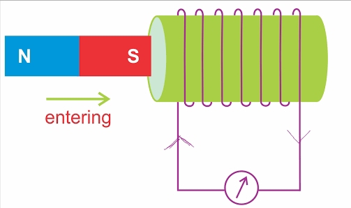
1. By moving a magnet with respect to the coil
If we move the north pole of strong bar magnet towards the end B of the coil. There is a momentary deflection in the needle of the galvanometer to the right. This indicates the presence of a current in the coil AB.
Now if we withdraw the north pole of the magnet away from the coil, the galvanometer is deflected toward the left, showing that the current is now set up in the direction opposite to the first.
The deflection becomes zero when the moment the motion of the magnet stops.
Now Place the magnet stationary at a point near to the coil, keeping its north pole towards the end B of the coil. We see that the galvanometer needle deflects toward the right when the coil is moved towards the north pole of the magnet.
Similarly the needle moves toward left when the coil is moved away.
When the coil is kept stationary with respect to the magnet, the deflection of the galvanometer drops to zero.
If we moved south pole of the magnet towards the end B of the coil, the deflections in the galvanometer is deflected toward the right.
If we withdraw the south pole of the magnet away from the coil, the galvanometer is deflected toward the left.
When the coil and the magnet are both stationary, then no current is induced in the coil and hence there is no deflection in the galvanometer.
Conclusion
• A moving magnet can be used to generate electric currents. • Motion of a magnet with respect to the coil produces an induced potential difference, which sets up an induced electric current in the circuit.• Moving a coil towards a magnet set up an electric current in the coil circuit as indicated by direction of galvanometer and needle.
• The direction of induced current can be reversed by reversing the direction of magnetic field.2. Current Carrying Coil and Simple coil
• Let us consider two different coils, Coil 1 and Coil 2 of copper wire having large number of turns inserting over a non-conducting cylindrical roll.
• Coil-1 having larger number of turns (100 turns) is connected in series with a battery and a plug key called primary coil and coil-2 having 50 turns is connected with a galvanometer called secondary coil.
• When the key is closed, the current in primary coil takes a little time to rise from 0 to a maximum value.
• As the current in the first coil changes, the magnetic field associated with it also changes. Thus the magnetic field lines around the secondary coil also change. Hence the change in magnetic field lines associated with the secondary coil induced electric current in it.
• When the key is closed the galvanometer shows deflection in its needle, the needle of the galvanometer instantly jumps to one side and just as quickly returns to zero, indicating a momentary current in coil-2.
• The same happens in the reverse direction when the key is opened.
• When coil 1 is disconnect from the battery, it is observe that the needle momentarily moves, but to the opposite side. It means that now the current flows in the opposite direction in coil-2.
• As the current in coil-1 reaches either a steady value or zero, the galvanometer in coil-2 shows no deflection i.e no current will induced in secondary coil.
Conclusion
• When the electric current through the coil–1 is changing (starting or stopping) a potential difference is induced in the coil-2.
Flemings Right Hand Rule
• This rule is used know the direction of the induced current.
• According to this rule "If we Stretch/Hold the thumb, forefinger and middle finger of right hand in such a way that they are perpendicular to each other, If the forefinger indicates the direction of the magnetic field and the thumb shows the direction of motion of conductor, then the middle finger will show the direction of induced current".


Comments
Post a Comment